PID Ball Balance Robot
Introduction
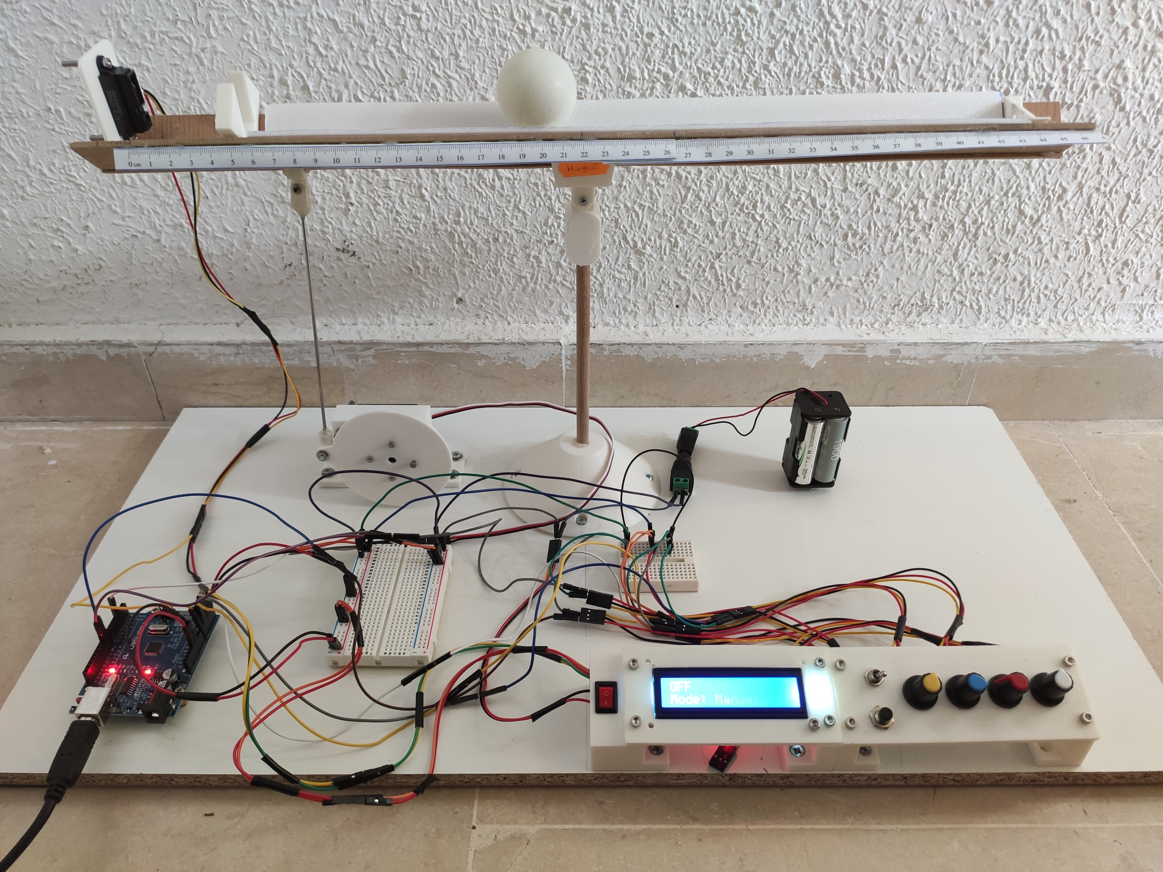
A self ball balance robot consists of a balance that can be tilted in two directions and a ball that moves on the balance. The basic principle is to control the position of the ball by changing the angle of the balance using a servo motor. This is commonly done using a PID controller and a distance sensor to measure the position of the ball. The goal usually is to keep the ball in the center of the plate. However, in this project a user control panel is added to the system to allow the user to control the final position of the ball manually as well as the controller gains and .
Part list and 3D design
As seen in the cover photo, the balance consists of a two piece wood pasted together and has a printed ruler to measure the position of the ball. The ball itself is a simple ping pong ball stopped in both ends by two 3D printed parts. The balance is attached to a central support that allows it to tilt in both directions. The servomotor is fixed in a 3D printed support and it is connected to the balance by a mechanism that controls the tilt angle. While some 3D printed parts are from the original design, others were designed to fit the project needs.
The unmodified parts are:
- The central hinge: 3D printed part that holds the balance
- The cone base: 3D printed part that holds the central hinge. Both parts are glued to a 8mm wood rod.
- The servo hinge: 3D printed part that holds the balance and is connected to the servo motor to control the tilt angle
- The servo disc: 3D printed part that connects the servo motor to the servo hinge
The new parts are:
- The IR sensor support: 3D printed part that holds the IR sensor in place with 2 screws.
- Closer stopper: 3D printed part that stop the ball to get closer than a certain distance from the IR sensor. As will see later, this is to avoid the ball to get closer than 6 cm and be able to uniquely measure the position of the ball.
- Servo motor support: 3D printed part that holds the servo motor. It was redesigned to fit the new servo motor used in this project.
- Control panel: 3D printed parts that hold the LCD display, 4 potentiometers, 1 button and 2 switches.
As seen in the following image the parts were designed in Catia V5 using the Part Design applying parametric design techniques. The 3D models were exported as STL files and sliced using Cura. Finally, all 3D printed parts were printed in a Artillery X1 3D printer using PLA filament
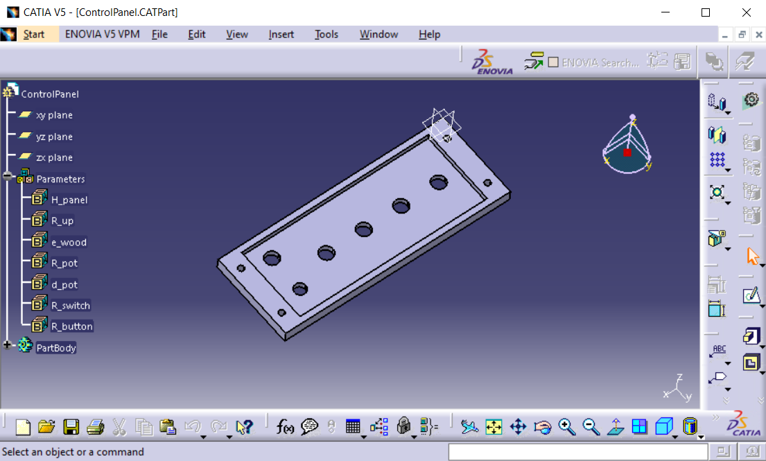
Control panel part in Catia V5
Extract data from image for IR sensor
To measure the position of the ball a IR sensor was used. The sensor is an ARCELI GP2Y0A21YK0F that outputs a voltage depending on the distance of the object in front of it. The sensor has a range of 10 to 80 cm as seen in the following graph from the Sharp datasheet. The following graph shows the voltage output of the sensor as a function of the distance of the object in front of it. As mentioned before, to ensure the sensor can uniquely measure the position of the ball, a closer stopper was added to avoid the ball to get closer than 6 cm from the sensor.
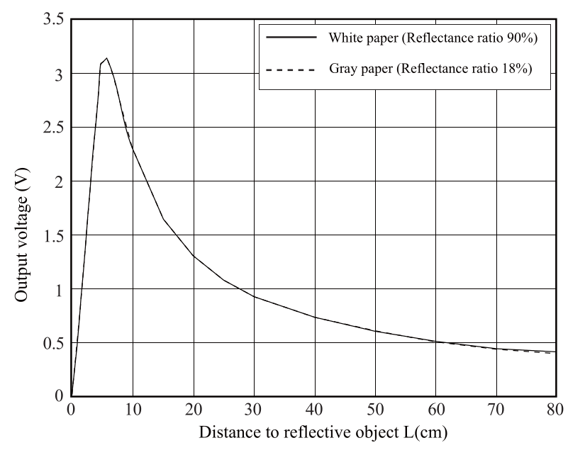
IR sensor Voltage vs Distance
The data from the sensor was extracted using ImageJ and a plugin call Figure Calibration. Once calibrated the plugin allows to extract data by clicking on the graph and save the data in a CSV file. The CSV file is then imported to a Python script that interpolates the data to get the distance of the ball from the sensor. The following image shows the data extracted from the graph and the interpolation of the data.
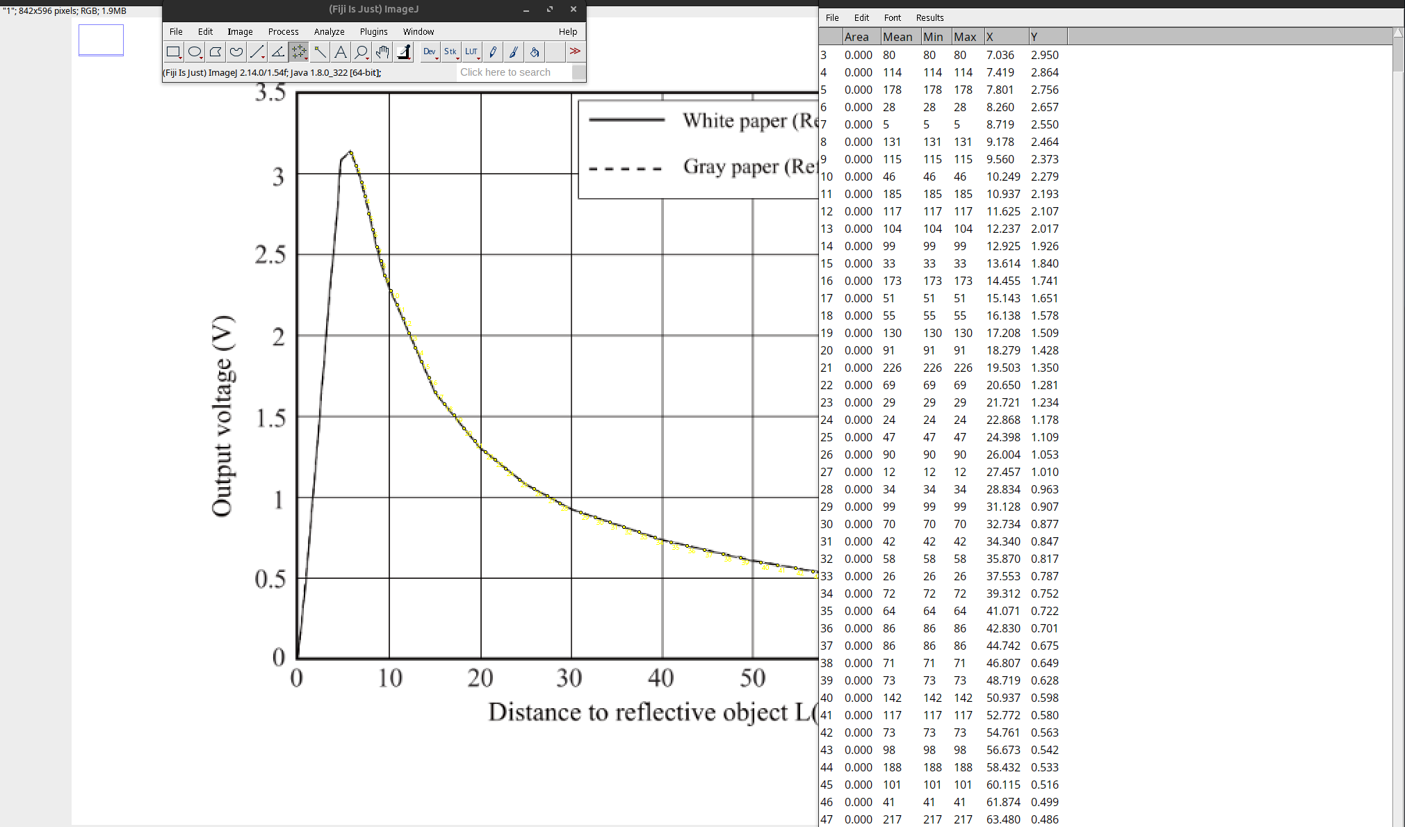
ImageJ data extraction
Once the data is extracted a python script was written to apply a curve fitting to the data. The following script uses the curve_fit function from the scipy.optimize library to fit the data to expression . The script then plots the data and the resulting curve.
import pandas as pd
import matplotlib.pyplot as plt
import numpy as np
from scipy.optimize import curve_fit

df = pd.read_csv("GP2Y0A21YK0F.csv")

# Split the data into d and V
x = df["V"].values
y = df["d"].values

coeff, _ = curve_fit(lambda v, a, b, c: a*(v**b)*np.exp(c*v),  x,  y,  p0=(4, 0.1, -0.01))
a2 = coeff[0]
b2 = coeff[1]
c2 = coeff[2]

# X values for the prediction
x_new = np.linspace(0.3, 4, 100)
y_new = a2*x_new**b2*np.exp(c2*x_new)

plt.scatter(x, y)
plt.plot(x_new, y_new, c="green", label=f"{round(a2, 4)} * (x^{round(b2, 4)}) * exp({round(c2, 4)} * x)")
plt.grid()
plt.xlabel("V [V]")
plt.ylabel("d [cm]")
plt.legend()
plt.show()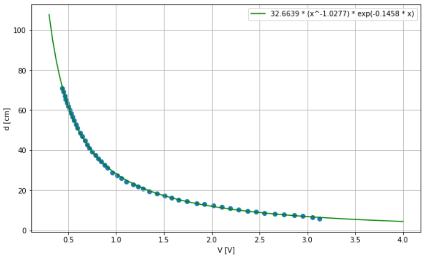
IR sensor Voltage vs Distance regression
Arduino Circuit
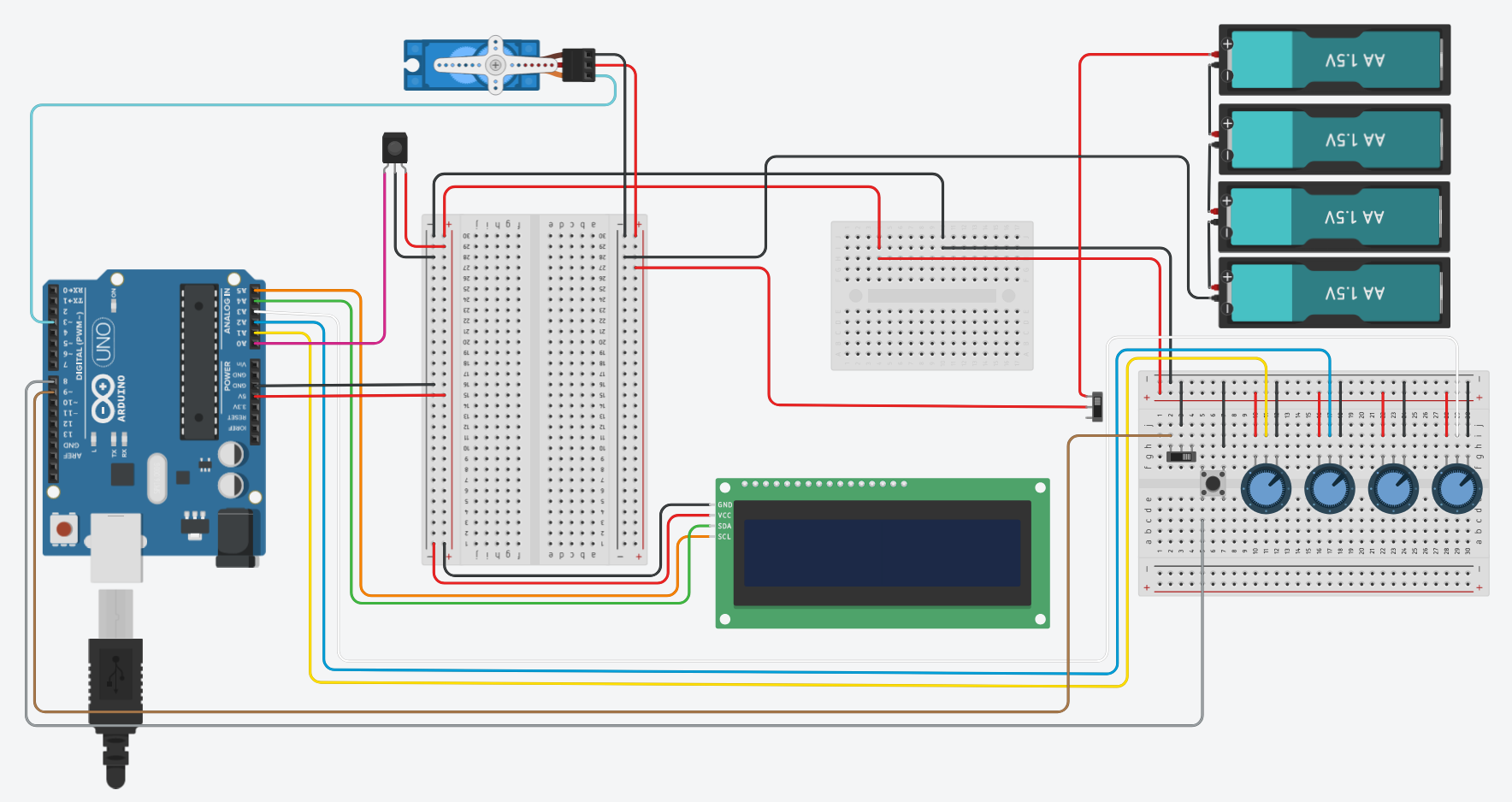
The complete circuit integrates the IR sensor, the servo motor, the LCD display, 4 potentiometers, 1 button and 2 switches. The following image shows the schematic of the circuit.
Circuit schematic
The Arduino UNO board is powered by a normal usb charger connected to the dc jack. Most of the components are powered by the 5V output of the Arduino. However a 4 AA battery pack is used to power the servo motor since it requires more current than the Arduino can provide in total.
Starting from the left, the IR sensor is connected to the analog pin A0 of the Arduino to read the voltage output of the sensor. The servo motor is connected to the PWM pin 3 of the Arduino and the 16x2 LCD display with an I2C interface is connected to the A4 (SDA) and A5(SCL) pins of the Arduino. This allows to use only 2 pins to communicate with the display rather than the 16 pins required by the normal interface.
About the user control panel, 3 potentiometers are connected to the analog pins A1, A2, A3 of the Arduino. Since the Arduino has only 6 analog pins, the potentiometer was not implemented. On the other hand, the button and a switch is connected to the digital pins 8 and 9 of the Arduino respectively. Finally the last switch is used to turn on the power supply of the servo motor so it is not connected to the Arduino.
The following image shows the final circuit assembled. The user input/output components are placed in a 3D printed control panel and all the components are connected using jumper wires and 2 breadboards. To do so most of the components were soldered to female headers in order to connect the jumper wires. Finally the 4 AA battery pack is fixed with a neodymium magnet to the table and can be easily removed to replace the batteries.
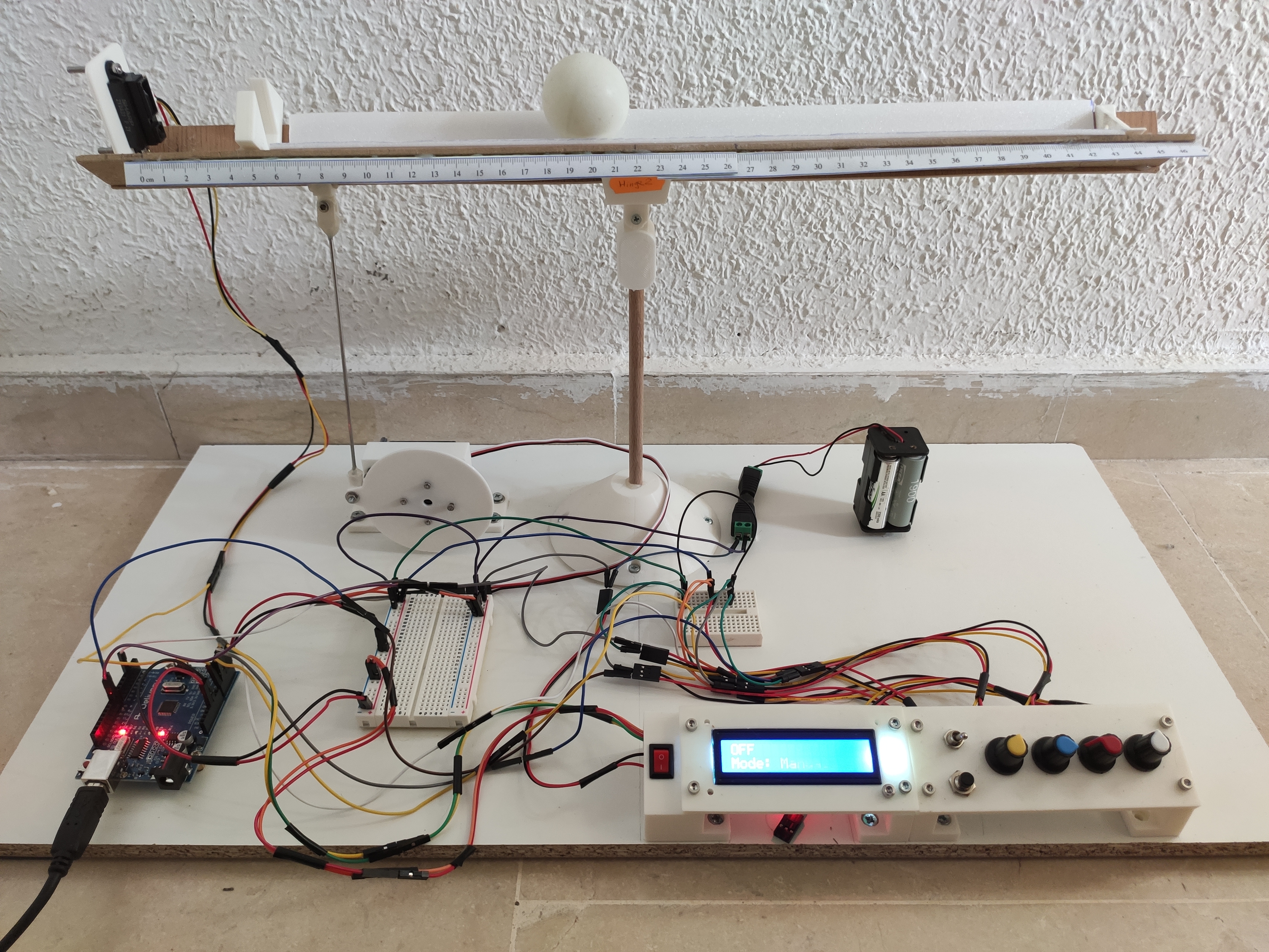
Circuit assembled
Programming
The Arduino code is divided in 3 main parts: the setup, the loop and the functions. First, the setup is executed once to initializes the components. Once the setup is done the loop is executed in a continuous loop. The loop reads the data from the IR sensor and the user control panel to control the servo motor. Last but not least, the functions are used to implement the distance measurement from the IR sensor and some sorting and filtering algorithms to reduce noise in the data.
In the top of the file the inputs/outputs pins are defined and the libraries are imported. It also defines the constants and variables used in the code like min, max and trim angles for the servo motor. This will be used to limit the movement of the servo motor and to set the balance in the middle position. The period variable is used to set the refresh rate of the main loop. The PID gains are also defined in this section. The trim values are the selected values of the PID constants and the min and max values are used to limit the values that the user can set using the potentiometers.
The setup initializes the digital and analog pins of the Arduino as well as the servo motor and the LCD display. It also initializes the variables used in the loop and the time variable to control the refresh rate of the loop.
In every iteration of the loop the code first reads the switch to select the mode of the controller. If the switch is on, the controller defined by user’s or preset gains changes the position of the servo motor to keep the ball in the setpoint distance. If the switch is off, the servomotor is set to trim position. While off, the user can change the mode of the controller by pressing the button. In manual mode the user can control the final position of the ball as well as the PID gains using the potentiometers, while in automatic mode the controller uses the preset PID gains an the user can only set the distance setpoint.
The LCD display is updated with the data read from the potentiometers and the IR sensor in order to get feedback of the system. When the switch is on, the distance to the ball is measured by get_distance function. This function reads the IR sensor n times and calculates the distance of the ball using the central 20% of the data. The data is sorted and filtered to reduce noise in the data. This is done by using the bubble sort algorithm and the central mean algorithm defined in bubbleSort and centralMean functions. Then the diference between the distance setpoint and the distance of the ball is calculated and used to calculate the PID control signal. The PID control signal is then used to set the servo motor to the new position. Finally the LCD display is updated with the new data.
#include <math.h>
#include <Servo.h>
#include <Wire.h>
#include <LiquidCrystal_I2C.h>


/////////////////// Inputs/outputs /////////////////////
#define SERVO_PIN 3 // Servomotor
#define SENSOR_PIN A0 // IR Distance sensor
#define POT_D A3 // Potentiometer to set distance setpoint
#define POT_kp A1 // Potentiometer to set kp
#define POT_kd A2 // Potentiometer to set kd
#define BUTTON 8 // Button input to switch
#define SWITCH 9 // Switch input

Servo myservo;  // create servo object to control a servo

// CONFIG:
int min_angle = 31; // Higher position 10
int max_angle = 97; // Lower position 106
int trim_angle = 64; // Balance position 63

///////////////////////////////////////////////////////

struct sensor_data {
  float distance;
  float volts;
};


////////////////////// Variables //////////////////////
int Read = 0;
float distance = 0.0;
float elapsedTime, time, timePrev; // Variables for time control
float distance_previous_error, distance_error;

// CONFIG:
int period = 50;  // Refresh rate period of the loop is 50ms
///////////////////////////////////////////////////////


////////////////// PID constants //////////////////////
// CONFIG:
float trim_kp=6; // Mine was 8
float trim_kd=550; // Mine was 3100, 600, 900 (cerca), 1000, 990, 1300, 1700 (casi) 400, 500 x
float trim_ki=0.2; // Mine was 0.2

float min_kp = 0.5 * trim_kp;
float max_kp = 2 * trim_kp;
float min_kd = 0.5 * trim_kd;
float max_kd = 2 * trim_kd;


float trim_setpoint = 22.5; // Should be the distance from sensor to the middle of the bar in mm
float min_setpoint = trim_setpoint - 10;
float max_setpoint = trim_setpoint + 10;


float PID_p, PID_i, PID_d, PID_total;
///////////////////////////////////////////////////////

//////////////////// LCD Config ///////////////////////
LiquidCrystal_I2C lcd(0x27,20,4);  //sometimes the LCD adress is not 0x3f. Change to 0x27 if it dosn't work.
int i = 0;
///////////////////////////////////////////////////////

//// Button setup ////
int lastButtonState = LOW;
int mode = 0;

void setup() {

    //// SERVO ////
    Serial.begin(9600);
    myservo.attach(SERVO_PIN);  // attaches the servo pin to the servo object

    myservo.write(min_angle);
    delay(1000);
    myservo.write(max_angle);
    delay(1000);
    myservo.write(trim_angle); // Put the servo at trim position, so the balance is in the middle
    delay(1000);

    //// IR Distance sensor ////
    pinMode(SENSOR_PIN, INPUT);

    //// POTENTIOMETERS ////
    pinMode(POT_D, INPUT);
    pinMode(POT_kp, INPUT);
    pinMode(POT_kd, INPUT);

    //// BUTTON AND SWITCH ////
    pinMode(BUTTON, INPUT);
    pinMode(SWITCH, INPUT_PULLUP);

    //// LCD 16X2 Display ////
    lcd.init(); // Init the LCD
    lcd.backlight(); // Activate backlight
    lcd.home();

    //// Variables setup ////
    time = millis();
}

void loop() {

    //// Read switch ////
    int switchState = digitalRead(SWITCH);

    if (switchState == HIGH) {

        // After each wait period
        if (millis() > time + period)
        {

            time = millis(); // Update time

            //// Read Potentiometers ////
            int pot_d = analogRead(POT_D);
            float distance_setpoint = map(pot_d, 0, 1023, min_setpoint, max_setpoint);

            float kp;
            float kd;
            float ki;
            if (mode == 0) {
                int pot_kp = analogRead(POT_kp);
                kp = map(pot_kp, 0, 1023, min_kp, max_kp);
                int pot_kd = analogRead(POT_kd);
                kd = map(pot_kd, 0, 1023, min_kd, max_kd);
                ki = trim_ki;
            }
            else {
                kp = trim_kp;
                kd = trim_kd;
                ki = trim_ki;
            }

            Serial.print("kp: ");
            Serial.print(kp);
            Serial.print(" kd: ");
            Serial.print(kd);

            //// Sensor ////
            sensor_data data = get_distance(100);
            float distance = data.distance;
            float volts = data.volts;

            //// Controller ////
            distance_error = distance_setpoint - distance; // 22.0 - d
            PID_p = kp * distance_error; // 10 x 8 = 80
            float dist_diference = distance_error - distance_previous_error;
            float speed = (distance_error - distance_previous_error)/period;
            PID_d = kd*(speed);

            // Filter to activate kD
            // if (abs(speed) < 0.01)
            // {
            //   PID_d = 0;
            // }

            // Filter to activate kI
            if(-3 < distance_error && distance_error < 3)
            {
                PID_i = PID_i + (ki * distance_error);
            }
            else
            {
                PID_i = 0;
            }

            PID_total = PID_p + PID_i + PID_d;
            Serial.print("PID: ");
            Serial.print(PID_total);
            PID_total = map(PID_total, -150, 150, max_angle, min_angle);

            if (PID_total < min_angle) {
                PID_total = min_angle;
            }
            if(PID_total > max_angle) {
                PID_total = max_angle;
            }

            Serial.print(" PID_total: ");
            Serial.println(PID_total);

            //// Actuator ////
            myservo.write(PID_total);

            //// Save current values ////
            distance_previous_error = distance_error;

            //// LCD Display ////
            // Turn off the display:
            lcd.clear();

            // First line: d, d_set
            //String m1 = "V: " + String(volts, 1) + " d: " + String(distance, 1);
            String m1_on = "d: " + String(distance, 1) + " set:" + String(distance_setpoint, 1);
            // Add distance and angle of the servo to a string, rounded to 2 decimal places
            // Print the message
            lcd.setCursor(0, 0);
            lcd.print(m1_on);

            // Second line: kp, kd, ki
            String m2_on = "kp:" + String(kp, 1) + " kd:" + String(kd, 0);
            //String m2 = "kp:" + String(kp, 1) + " kd:" + String(kd, 0) + " ki:" + String(ki, 1);
            lcd.setCursor(0, 1);
            lcd.print(m2_on);


            // Serial.print("D: ");
            // Serial.println(distance);
            // Serial.print("set:");
            // Serial.println(distance_setpoint);
        }

    }
    else {
        //// Stop the servo ////
        myservo.write(trim_angle);

        //// Read Button ////
        int buttonState = digitalRead(BUTTON);

        if (buttonState == LOW && lastButtonState == HIGH) {
            if (mode == 0) {
                mode = 1;
            } else {
                mode = 0;
            }

            Serial.print("PUSHED Mode: ");
            Serial.println(mode);
        }

        lastButtonState = buttonState;

        lcd.clear();
        String m1 = "OFF";
        lcd.setCursor(0, 0);
        lcd.print(m1);
        String m2_off;
        if (mode == 0) {
            m2_off = "Mode: Manual";
        }
        else {
            m2_off = "Mode: Preset";
        }

        lcd.setCursor(0, 1);
        lcd.print(m2_off);

        // Serial.print("Mode: ");
        // Serial.println(m2_off);
    }
}


sensor_data get_distance(int n) {

    // Read analog pin n times and sum Analog Data
    long sumAD = 0;
    long ADarray[n];
    for (int i=0; i<n; i++) {
        long AD_read = analogRead(SENSOR_PIN);
        sumAD = sumAD + AD_read; // Read (0 - 1023) <-> (0V - 3.3 V)
        ADarray[i] = AD_read;
    }

    //float aData = sumAD / n; // Mean value of Analog Data

    bubbleSort(n, ADarray); // Sort measurements
    //float aData = median(n, ADarray); // Use median value
    float aData = centralMean(n, ADarray, 0.5); // Use 20% of central data for average

    // Calculate volts mapping analog data (0 - 1023) to read voltage (0 - 3.3 V)
    //float volts = map(aData, 0, 1023, 0, 3.3); // Map from 0 - 1023 to 0 - 3.3 V
    //float volts = aData * 2 / 1024;
    float volts = aData * 3.3 / 1024; // Map from 0 - 1023 to 0 - 3.3 V


    // Calculate distance base on a*t^b*e(c*t) regression from documentation data
    float a = 32.6639;
    float b = -1.0277;
    float c = -0.1458;
    float offset = -2.5; // To center
    float distance = a * pow(volts, b) * exp(c * volts) + offset; // regression evaluation

    // Serial Communication
    Serial.print(volts);
    Serial.println(" V ");

    sensor_data data;

    data.distance = distance;
    data.volts = volts;
    return data;
}

void printArray(int N, long arr[])
{
    for (int i=0; i < N; i++)
    {
        Serial.print(arr[i]);
        Serial.print(" ");
    }
    Serial.print("\n");
}

void bubbleSort(int N, long arr[])
{
    for (int i=0; i < N; i++)
    {
        int changes = 0;
        for (int j=0; j < N-i-1; j++)
        {
            if (arr[j] > arr[j+1])
            {
            long val1 = arr[j];
            long val2 = arr[j+1];
            arr[j] = val2;
            arr[j+1] = val1;
            changes = changes + 1;
            }
        }
        if (changes == 0)
        {
            break;
        }
    }
}

long median(int N, long arr[])
{
    if (N % 2 == 0)
    {
        int idx = N/2;
        return (arr[idx - 1] + arr[idx])/2;
    }
    else
    {
        int idx = (N - 1) / 2;
        return arr[idx];
    }
}

float centralMean(int N, long arr[], float r)
{
    long centralSum = 0;
    int nC = (int) N * r;

    if (N % 2 == 0)
    {
        if (nC % 2 != 0)
        {
            nC = nC - 1;
        }
        // x|x|o|x
        for (int i = (N/2 - nC/2); i < (N/2 + nC/2); i++)
        {
            centralSum += arr[i];
            // Serial.println(arr[i]);
        }
    }
    else
    {
        if (nC % 2 == 0)
        {
            nC = nC - 1;
        }
        // x|o|x
        for (int i = (N/2 - (nC-1)/2); i < ((N-1)/2 + (nC-1)/2 + 1); i++)
        {
            centralSum += arr[i];
            Serial.println(arr[i]);
        }
    }

    // Serial.print("n: ");
    // Serial.println(nC);

    return (float) centralSum / (float) nC;
}